
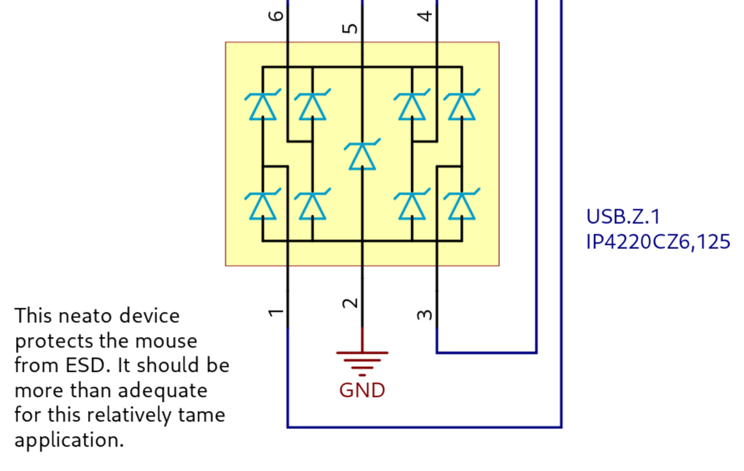
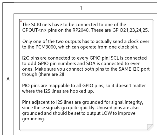
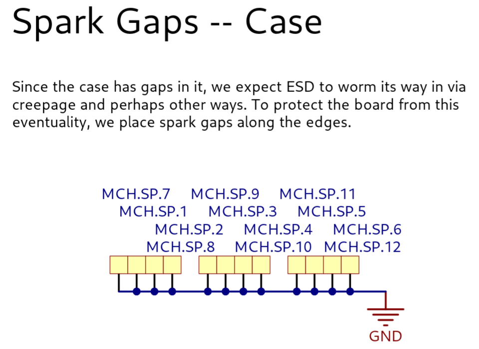
found a great example of pcb schematics with pedagogical notes on! check out this detail zoom from the ploopy a+ schematics
i have been amateurishly attempting circuit board designs now and then for years and i had never even heard of a spark gap or seen one in a schematic, much less explained there, before today
if you know of more like this, made with the education of amateur pcb designers in mind, please post them!
big thanks for posting photos of the device @gbrnt that led me to this info
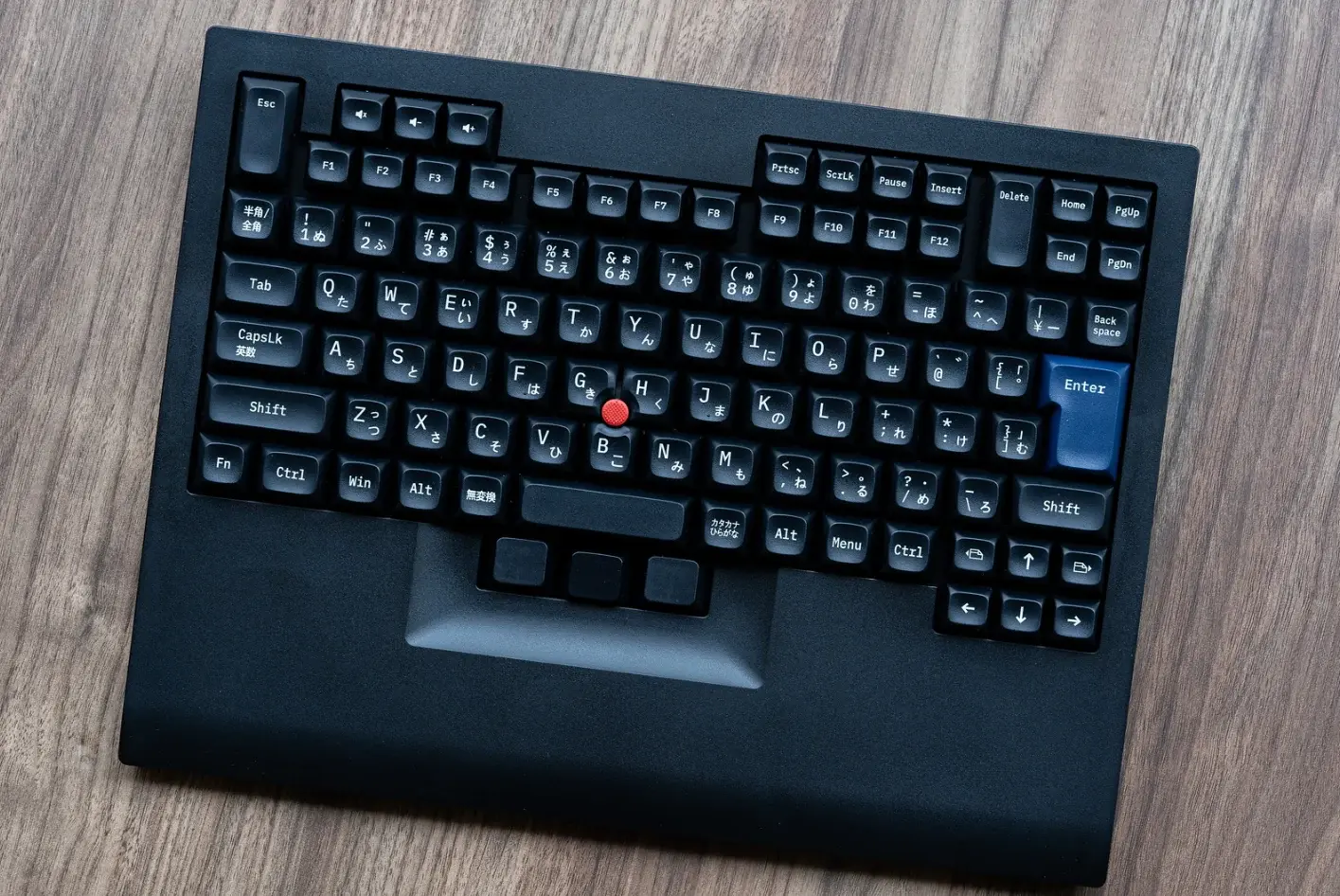
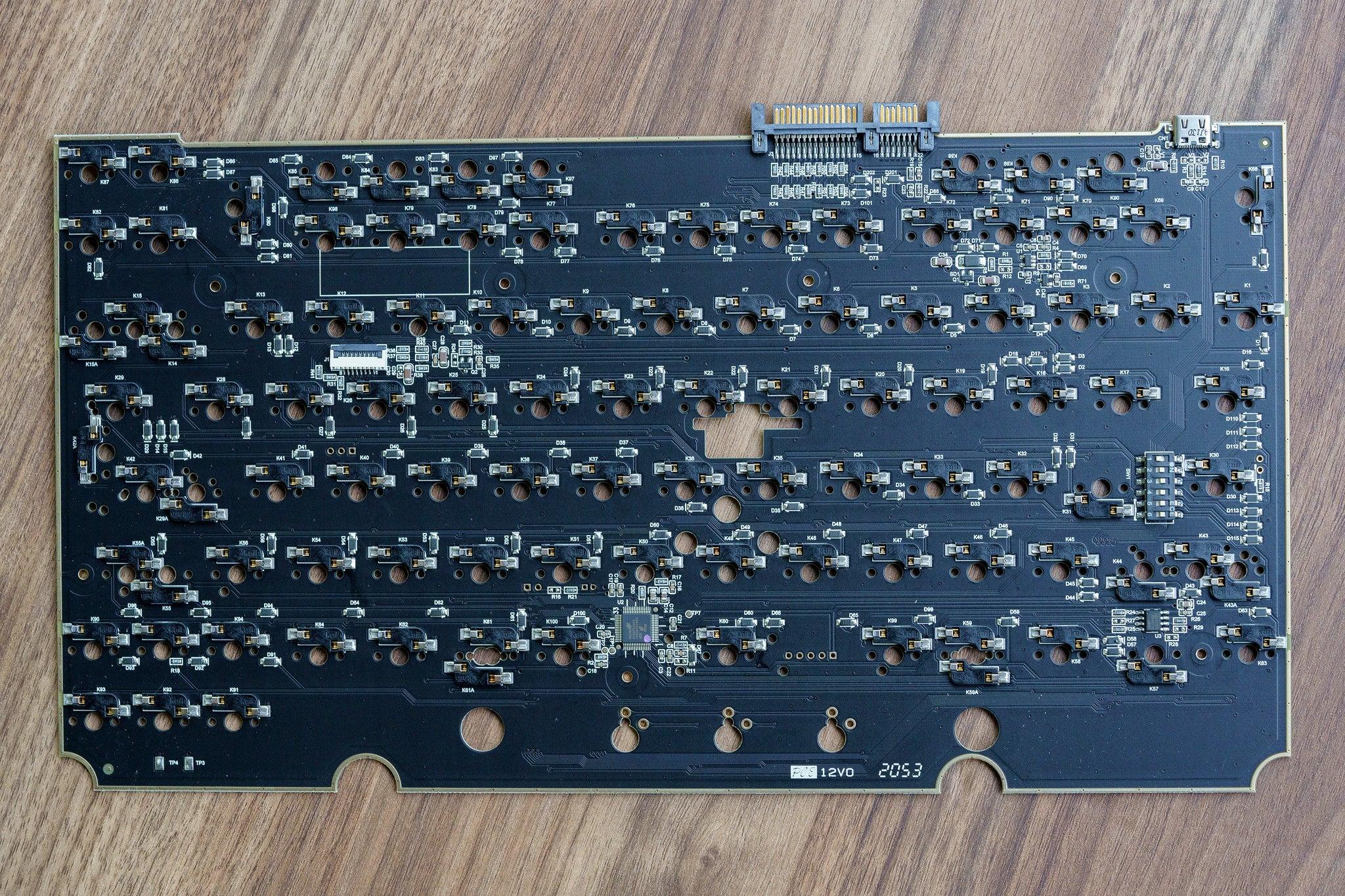
finally found an example of a keyboard pcb that uses spark gaps. no schematic, but you can see it in the photo. this is a tex shinobi
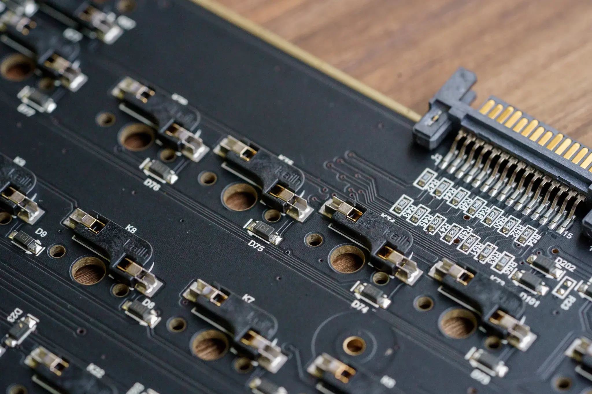
also visible: is that a sata edge connector? what the heck for? i don't see it mentioned in the user manual. some of their boards have a bluetooth add-on module, maybe that's it
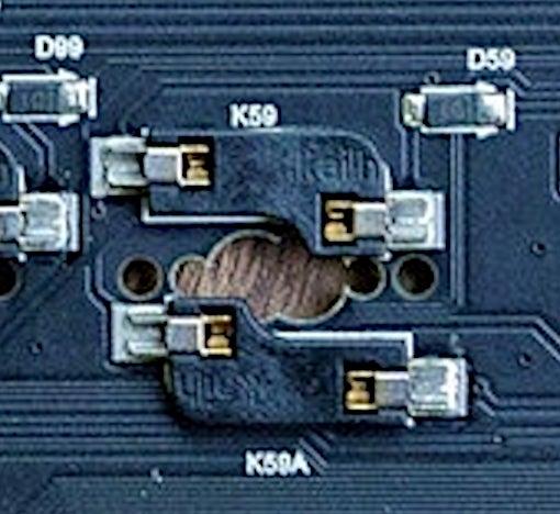
this seems weird
would jlcpcb pcb assembly build this for me? i was assuming they wouldn't because of the overlapping drill hits
but also
if you shove a keyswitch into one of these won't its center pin knock the other one off the board??
if both of those are non-issues, i can offer more options in my own keyboard design
keyboard pcb design project
wow somehow i didn't notice until now the very detailed writeup of the ErgoNICE complete with beautiful schematic by @valpackett who also made tiddlypwa that i keep my whole life inside of. 😲
ergonice uses an stm32 microcontroller like mine!
she chose horizon eda instead of kicad and praises it highly. i just checked and it has a much better llm policy too. time to switch!
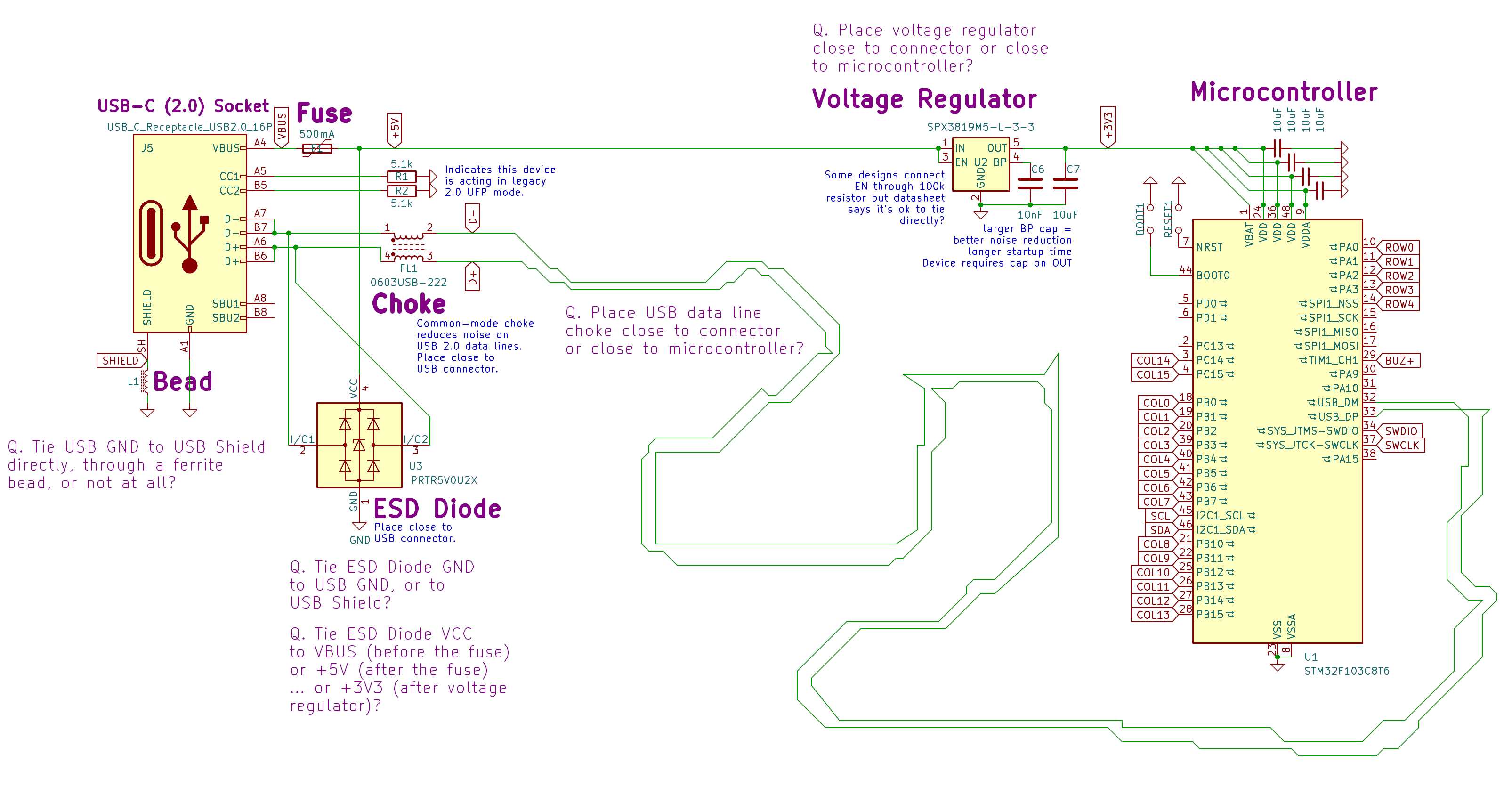
hello electronics knowers! would anybody care to give me a couple newbie pointers?
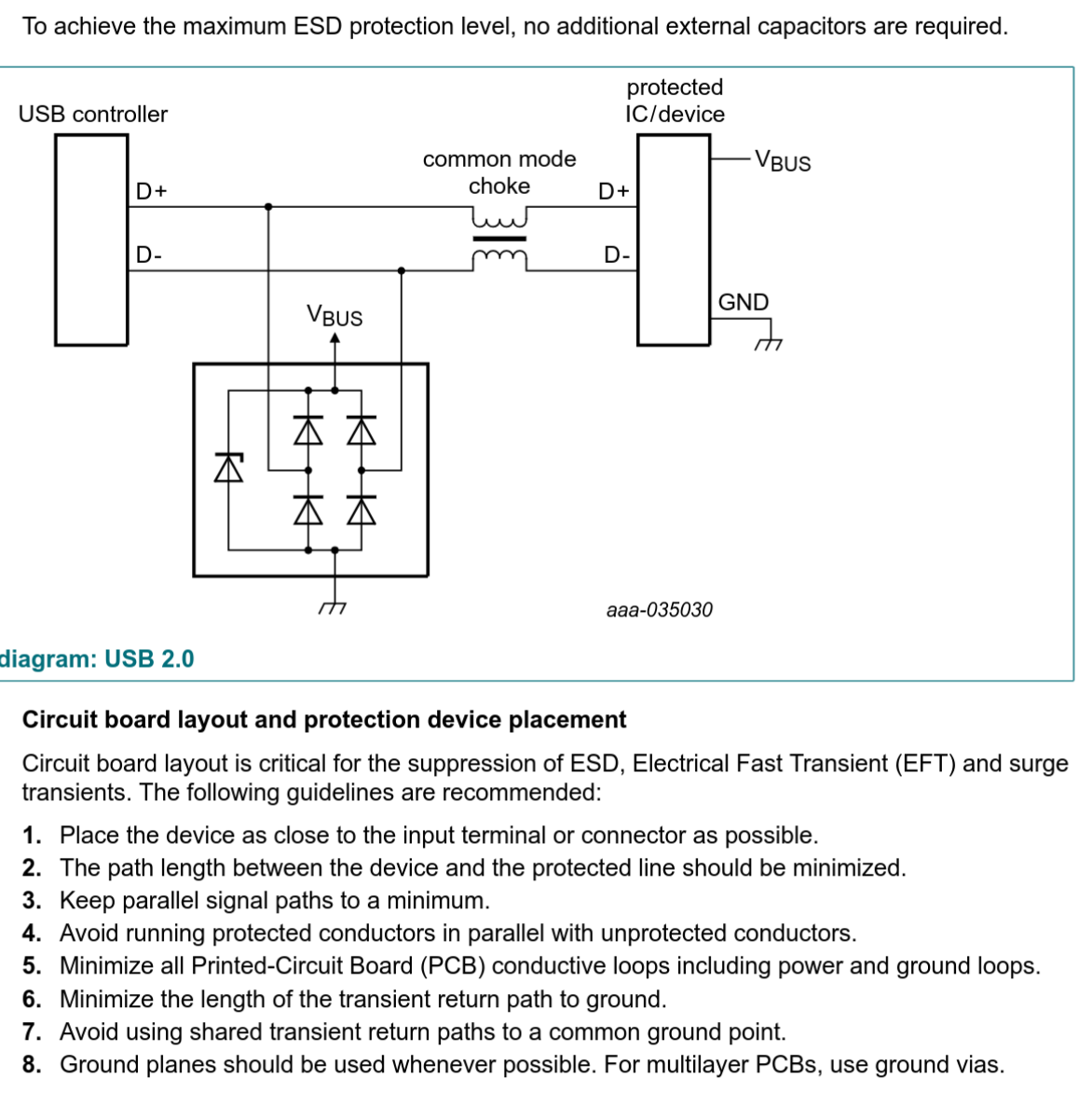
i'm trying to hook up a (stm32f) microcontroller to a usb socket in a safe-ish way. copying from others' designs i have an esd protection diode, a common mode choke, a fuse, a voltage regulator, a ferrite bead. no reverse polarity protection because no battery
got some questions, as seen on my simplified schematic, e.g.: should the fuse protect the esd diode? should the choke be close to the microcontroller?


@Satsuma i think it's something like,
a standard-ish package size is
0.04 x 0.02 in
which abbreviates as 0402 (imperial)
and is equivalent to
1.0 x 0.5 mm
which abbreviates to 1005 (metric)
meanwhile 0402 (metric) means
0.4 x 0.2 mm
which is equivalent to
0.016 x 0.008 in
... so,
... huh
why do they call that 01005 (imperial)?
i guess it's close to
0.01 x 0.005 in
okay i have no idea